Calibration Overview
Channels of data collected by cavg or cap can be named and their amplitudes calibrated into user-defined units by the calibrate program.
Real world units can be specified for any channel. A/D units are remapped into other units (the default units are microvolts). For example, a channel can be named “Pressure” with units scaled as (mV = mmHg). Note that only the analysis program can make use of these other units, qm and other programs will only show Y scales in mV. The scaling of mv to A/D units can, however, be changed and these scaled units will be displayed by all programs (see the example calfile below).
While calibrate can write files with other names, default.cal is the only file that can be used by cavg and cap. These programs look in the current directory for default.cal and if not found use the version of default.cal located in /usr/neuro/lib. Calibration files with other names must be renamed to default.cal (or copied into default.cal) before being accessible to the capture programs.
cp dualintra.cal default.cal
The contents of default.cal are written into the header of each data run captured (at the start of the “.frm” file). Programs that displayed captured data (qm, analysis, peel, etc.) use the calibration information contained in the run header. They cannot use the information in default.cal.
Certain environment variables have a special meaning to calibrate, and to the capture programs. These environment variables specify parameters related to the type of A/D converter used. All of these environment variables should be set in your “.profile” or “.login” file and are set for the A/D converter on your system. Do not change them!
Defining calibration information before the data is collected.
Channel names and calibration are usually assigned before data capture by use of the calibrate program run from the shell:
calibrate [calfile]
Calibrate allows specifying calibration information for all A/D channels in a calibration file, for later use by the data capture programs or to change this information in an existing calibration file. The sole task of the calibrate program is to create a file called default.cal. The optional argument, calfile, specifies the calibration file to be modified (default is “default.cal” in the current directory).
Users may also change channel names for the next data capture (run file) from within the cap program by clicking on the channel name field.
Modifying calibration information after data is collected.
Channel names, calibration and units can be modified after data capture in two ways. The contents of default.cal can be edited and the updated information “forced” into the run headers of one or several run files. After editing the calibration file (e.g. “default.cal”) the program called fixcal is used.
fixcal -f cell[2-9].frm
Updates the headers in files called “cell2.frm cell3.frm …. cell8.frm cell9.frm” with the information in the current default.cal file. Note the “-f”.
Channel names, calibration and units can also be changed in the run file currently being analyzed from within the analysis program. This is done under the calibrate section of the main menu in analysis. Changes only affect the current run file.
Calibrate Menus and Commands
When invoked, calibrate displays the current contents of default.cal and prints the following menu prompt line:
Calibrate Edit Gain Import Name Print Quit View-settings Write
Calibrate calibrates voltage levels for a channel. You are prompted for a channel number (0-15 for 16-channel A/D, or 0-63 for 64-channel A/D), from which the calibration levels will be sampled. Hitting RETURN after the next prompt causes the software to sample from that selected channels and to define the voltage level on the channel as “zero”.
The correspondence between A/D units and a user-specified signal can be calculated using the height of a pulse or from a DC signal. Answering No to the pulse/level prompt causes the software to treat the voltage of the specified input channel as a DC level relative to the previously determined baseline (zero) level. To determine the calibration level from a pulse, answer Y, or RETURN (default response). You are then prompted for the pulse triggering threshold (in A/D units; use the default value) You will rarely have to change this threshold but you may specify a smaller threshold value if previous attempts failed to find a pulse, or a larger value if you suspect that noise previously caused false-triggering. After the RETURN the software scans the selected channel looking for a pulse. It stops when one is found or when ten seconds have elapsed. You are finally prompted for the size (LEVEL) of the signal used for calibration in microvolts.
Calibrating a Channel with a Calibration Pulse
We can calibrate an input channel by sampling a pulse of a predetermined voltage level. By sampling before the pulse, we can determine the A/D input value that corresponds to zero volts (Z). By then sampling the pulse at its peak (H), and specifying the voltage level of that pulse in microvolts (L), we can then determine the voltabe level (V) for any input sample (S) with the formula:V = (S-Z) x L / H / 1,000,000
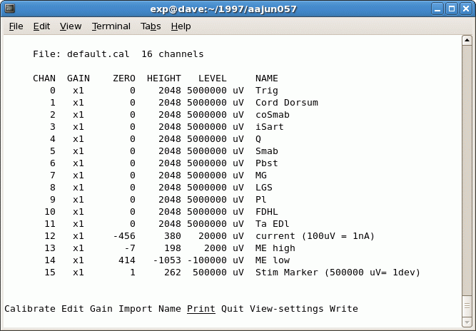
This is a screen shot of calibrate, showing a sample calibration file (e.g. default.cal):
In the sample file, channels 0-11 have a Zero value of 0 and a height of 2048 A/D units. This probably means that they were not calibrated and were left at their default values. Default values for 12-bit A/D boards are zero (middle of the A/D range which is ±5 V) and the height is positive full scale (2048 A/D units). For a 16-bit A/D board, the positive full scale height is 32767 units. The names are for user convenience and entered using the Name option.
Channel 12 (current monitor) was calibrated using a 20 nA pulse. The user followed the prompts given under the “calibrate” menu item and the calibrate program determined the “zero” and “height” readings by digitizing the pulse. The user entered the level as “20000uV”. This (arbitrary) number now allows a simple re-mapping of mV to nA. Information in the name field “ME current (1000uV= 1nA)” converts the amplitude of the 20 nA current pulse (i.e. LEVEL) into 1 mV units (i. e divides the calibration level by 20). Now when qm (or other programs) display this trace (or waveform) there will be a correspondence of one mV to one nA. Remember that only analysis will show the units as nA.
Channel 13 (the high gain microelectrode) was calibrated using a 2 mV cal pulse (2000 uV). Calibration of channel 14 gave a zero for channel 14 of 325 A/D units ( this represents an offset of 325/2048 * 5 V full scale = +.79 V). A -100 mV DC signal (-100000 uV) was used for Channel 14 calibration. The calibration for Channel 15 has been converted to other units (“devs”) by the bracketed assignment of 1/10 the positive range of the A/D (1/10 * 5V = 500000 uV) to 1 “dev”.
Edit manually modifies channel calibration information. Values for gain, zero, and height are entered from the keyboard.
Gain allows modifying the gain factor for a channel, or for all channels. This is not supported on the QNX systems.
Import replaces all information in the current calibration file with that in another file. You are prompted for a file name.
Name assigns names to channels. Names can be up to 42 characters long and are for user convenience. While the names are ignored by the software, programs make use of re-mapping information contained in the name fields (see the example above).
Print prints the calibration information displayed on screen. In the Print menu, File allows storing calibration information in a printable ASCII text file. Printer prints calibration information on the printer using the lpr program. Ensure the printer is powered up, on-line, and ready to print. Video produces a printed copy of the video display’s current contents (i.e. a screen dump) using the sdump program. Typing Control-B does the same thing but the “Print/Video” operation can be used when the program is reading its commands from a file, rather than the terminal. “Print/Video” also clears the menu area before performing the screen dump.
Quit terminates the program, giving you the option to Write out any changes you’ve made to the calibration information.
View-settings prints out the current calibration information for each of the channels. The values printed are the gain factor, the zero and peak levels in A/D units, the calibration level in microvolts, and the name for each channel. This operation will refresh the screen when it is cleared by a shell escape.
Write writes calibration information to a file.
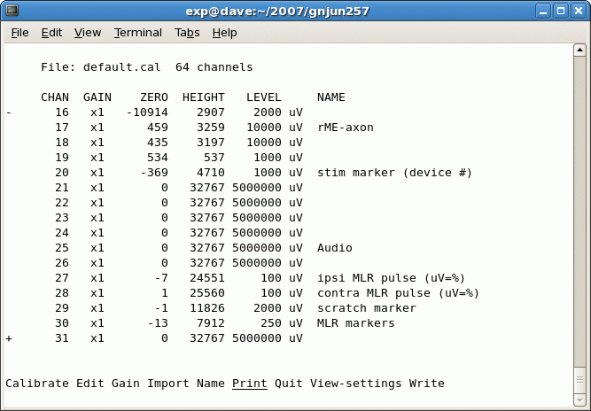
+ or – keys, or the up and down arrow keys, scroll through the list of channels currently displayed. If there are more channels on your A/D converter, or in the current calibration file, than can be displayed on a single screen, only a partial set of channels will be shown, and you have to scroll to see other channels.
This is a screen shot of calibrate showing part of a 64-channel calibration file:


